Многоканальный монитор с интеллектуальным управлением KM1
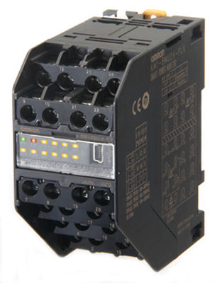
Многоканальный монитор с интеллектуальным управлением
Платформа KM1 позволяет визуализировать потребление электроэнергии при использовании на задней панели с помощью концепции "ведущий-ведомый". К ведущему блоку можно подключить до четырех ведомых для осуществления одновременного измерения электрических и неэлектрических параметров.
- Существенно сокращено время установки.
- Пространство для установки уменьшено на 24% по сравнению с традиционными средствами для контроля.
- Уменьшено количество устройств: с помощью одной платформы можно измерить до 36 контуров.
- Количество проводных соединений также уменьшено благодаря высокоскоростному соединению внутренней шины Innerbus и напряжению источника питания ведущего блока.
- Настраиваемая платформа для любой области применения
- Удобная классификация объединенной энергосистемы благодаря настраиваемым внутренним пороговым значениям
- Высокоточные измерения даже для токов ниже 5% от номинального значения.
- Отсутствие необходимости использовать трансформатор напряжения / До 7 импульсных выходов для сбора данных, в том числе, о неэлектрических параметрах
- Оснащен входом температуры
- Бесплатная программа для конфигурации KM//KE1
- Двойной мониторинг системы с помощью одного блока
Заказная информация
Smart power monitors
| Unit type | Unit category | Power supply voltage | Communications | Order code |
|---|---|---|---|---|
| Dual power system measurement unit | Measurement master | 100 to 240 VAC | RS-485 | KM1-PMU2A-FLK |
| Power measurement unit | KM1-PMU1A-FLK | |||
| Pulse/temperature input unit | Function slave | KM1-EMU8A-FLK | ||
| CT extension unit | CT extension slave | Power supplied from the measurement master unit | - | KE1-CTD8E |
| DeviceNet communications unit | Communications slave | 100 to 240 VAC | RS-485 or DeviceNet | KE1-DRT-FLK |
Options (Order separately)
Separate or In-panel current transformer (CT)
| Rated primary current | Rated secondary current | Installation | Order code |
|---|---|---|---|
| 5 A | Special output | Installed separately | KM20-CTF-5A |
| 50 A | KM20-CTF-50A | ||
| 100 A | KM20-CTF-100A | ||
| 200 A | KM20-CTF-200A | ||
| 400 A | KM20-CTF-400A | ||
| 600 A | KM20-CTF-600A | ||
| 5 A/50 A | In-panel (penetration type) | KM20-CTB-5A/50A |
Note: CT cables are not included with the CTs.
Current transformer (CT) cable
| Specification | Order code |
|---|---|
| 3-m cable | KM20-CTF-CB3 |
Note: Use the CT cable specified by OMRON or one manufactured by JST Mfg. Co. You can also use a 1.25-B3A crimping terminal or AWG22 power cable.
Related devices (Sold separately)
Communications interface converter
| Dimensions (mm) | Communications conversion | Power supply voltage | Order code |
|---|---|---|---|
| 30 x 80 x 78 (WxHxD) | RS-232C, USB <-> Half-duplex RS-485 | 100 to 240 VAC | K3SC-10 AC100-240 |
| 24 VAC/DC | K3SC-10 AC/DC24 |
Характеристики
Ratings
| Item | Master unit | Slave unit | |||
|---|---|---|---|---|---|
| KM1-PMU2A-FLK (Dual power systems) |
KM1-PMU1A-FLK (Single power system) |
KM1-EMU8A-FLK (Pulses/temperatures) |
KE1-CTD8E (CT extension unit) |
||
| Applicable phase wiring method | Single-phase two wire, single-phase three wire and three-phase three wire | Single-phase two wire, single-phase three wire, three-phase three wire and three-phase four wire | - | Single-phase two wire, single-phase three wire, three-phase three wire and three-phase four wire | |
| Maximum number of CT connections | 4 | 3 | - | 8 | |
| Selectable types of CT capacities | 2 types | 1 type | - | Two types per Slave Unit | |
| Power supply | Rated power supply voltage | 100 to 240 VAC, 50/60 Hz | - | ||
| Allowable supply voltage range | 85% to 110% of rated power supply voltage | - | |||
| Power supply allowable frequency range | 45 to 65 Hz | - | |||
| Power consumption | Standalone: 10 VA max., Maximum expansion: 14 VA max. | 10 VA max. | - | ||
| Input | Rated input voltage | 100 to 480 VAC (single-phase, 2-wire): Line voltage 100/200 VAC (single-phase, 3-wire): Phase voltage/line voltage 100 to 480 VAC (3-phase, 3-wire): Line voltage |
100 to 480 VAC (single-phase, 2-wire): Line voltage 100/200 VAC (single-phase, 3-wire): Phase voltage/line voltage 100 to 480 VAC (3-phase, 3-wire): Line voltage 58 to 277 VAC (3-phase, 4-wire): Phase voltage |
- | |
| Rated input current (CT) | (5, 50, 100, 200, 400, or 600 A) | - | (5, 50, 100, 200, 400, or 600 A) | ||
| Rated input power | With 5-A CT: 4 kW With 50-A CT: 40 kW With 100-A CT: 80 kW With 200-A CT: 160 kW With 400-A CT: 320 kW With 600-A CT: 480 kW |
- | |||
| Rated input frequency | 50/60 Hz | - | |||
| Allowable input frequency range | 45 to 65 Hz | - | |||
| Allowable input voltage | 110% of rated input voltage (continuous) | - | |||
| Allowable input current | 120% of rated input current (continuous) | - | 120% of rated input current (continuous) | ||
| Ambient operating temperature | −10 to 55°C (with no condensation or icing) | ||||
| Storage temperature | −25 to 65°C (with no condensation or icing) | ||||
| Ambient operating humidity | 25% to 85% | ||||
| Storage humidity | 25% to 85% | ||||
| Altitude | 2,000 m max. | ||||
Performance
| Item | Master unit | Slave unit | |||
|---|---|---|---|---|---|
| KM1-PMU2A-FLK (Dual power systems) |
KM1-PMU1A-FLK (Single power system) |
KM1-EMU8A-FLK (Pulses/temperatures) |
KE1-CTD8E (CT extension unit) |
||
| Accuracy | Voltage | ±1.0% FS, ±1 digit; or, ±2.0% FS, ±1 digit for voltage across Vtr under the same conditions | - | ||
| Current | ±1.0% FS, ±1 digit However, the accuracy is ±2.0% FS, ±1 digit for the phase-S current for a three-phase, three wire circuit and the phase-N current for a single-phase, three wire circuit under the same conditions. |
- | ±1.0% FS, ±1 digit | ||
| However, the accuracy is ±2.0% FS, ±1 digit for the phase-S current for a three-phase, three wire circuit and the phase-N current for a single-phase, three wire circuit under the same conditions. | |||||
| Power (active power and reactive power) | Active power and reactive power ±2.0% FS, ±1 digit (Power factor = 1) |
- | Active power and reactive power ±2.0% FS, ±1 digit (Power factor = 1) |
||
| Frequency | ±0.3 Hz ±1 digit | - | |||
| Power factor | ±5.0% FS at an ambient temperature of 23° C, rated input, rated frequency, and a power factor of 0.5 to 1 to 0.5 | - | ±5.0% FS at an ambient temperature of 23° C, rated input, rated frequency, and a power factor of 0.5 to 1 to 0.5 | ||
| Temperature | - | ±5°C two hours after the power supply is turned ON (after performing any adjustments for the ambient temperature) | - | ||
| RS-485 | Protocols | Communications protocol setting: Compoway/F or Modbus | |||
| Sync method | Start-stop | ||||
| Node number setting | CompoWay/F: 0 to 99, Modbus:1 to 99 When a switch operation is performed to set the protocol to Modbus when the node number is set to 0, the node number is automatically changed to 1. |
||||
| Baud rate | 9,600 bps, 19,200 bps, or 38,400 bps | ||||
| Transmission code | CompoWay/F: ASCII, Modbus: Binary | ||||
| Data length | CompoWay/F: 7 bits, 8 bits; Modbus: 8 bits | ||||
| Stop bits | CompoWay/F: 1 bits or 2 bits; Modbus: 1 bit with priority, 2 bits without priority | ||||
| Parity | Even, odd, or none | ||||
| Maximum transmission distance | 500 m | ||||
| Maximum number of nodes | CompoWay/F: 31, Modbus: 99 | ||||
| Communication items | Refer to the relevant communication specification manuals | ||||
| USB | USB 1.1 compatible | ||||
Special CTs
Current Transformer (CT) Cable
| Configuration | Installed separately | In-panel (penetration type) |
|||||
|---|---|---|---|---|---|---|---|
| Model | KM20-CTF-5A | KM20-CTF-50A | KM20-CTF-100A | KM20-CTF-200A | KM20-CTF-400A | KM20-CTF-600A | KM20-CTB-5A/50A |
| Rated primary current | 5 A | 50 A | 100 A | 200 A | 400 A | 600 A | 5 A/50 A |
| Rated secondary current | 1.67 mA | 1.67 mA | 33.3 mA | 66.7 mA | 66.7 mA | 66.7 mA | 1.67 mA/16.7 mA |
| Secondary winding | 3,000 turns | 6,000 turns | 9,000 turns | 3,000 turns | |||
| Applicable frequency | 10 Hz to 5 kHz | ||||||
| Insulation resistance | Between output terminals and case: 50 MΩ min. (at 500 VDC) | ||||||
| Dielectric strength | Between output terminals and case: 2,000 VAC for 1 minute | ||||||
| Protective element | 7.5-V clamp element | ||||||
| Allowable number of connections/disconnections | 100 times | ||||||
| Inner diameter (mm) | 10 | 16 | 24 | 37 | 10 | ||
| Operating temperature and humidity ranges | −20 to 60° C, 85% max. (with no condensation) | ||||||
| Storage temperature and humidity ranges | −30 to 65° C, 85% max. (with no condensation) | ||||||
KM-series Power monitor models
| Series name | KM1 Series | |||
|---|---|---|---|---|
| Model | KM1-PMU_A-FLK | KE1-CTD8E | KM1-EMU8A-FLK | |
| Dimensions (mm) | 45 x 96 x 90 (WxHxD) (maximum width of 45 x 5 when five Units are linked together) |
|||
| Applicable phase wiring method | Single-phase, two wire | OK | OK | - |
| Single-phase, three wire | OK | OK | - | |
| Three-phase, three wire | OK | OK | - | |
| Three-phase, four wire | PMU1A only | OK | - | |
| 400-V direct measurement | OK | - | - | |
| Power Monitor power supply | 100 to 240 VAC | Provided from the Master Unit | 100 to 240 VAC | |
| Measured items | Total power consumption | OK | OK | - |
| Active power | OK | OK | - | |
| Instantaneous reactive power | OK | OK | - | |
| Current | OK | OK | - | |
| Voltage | OK | - | - | |
| Power factor | OK | OK | - | |
| Frequency | OK | - | - | |
| Pulse count | - | - | OK (Can be changed with event input.) | |
| Temperature | - | - | OK | |
KE1-DRT-FLK DeviceNet communications unit
| Item | Specification | |||
|---|---|---|---|---|
| Communications |
|
|||
| Connection configuration | Can be a combination of multidrops and T-branching (for both main and branch lines). | |||
| Baud rate | 500, 250, or 125 kbps (automatically detected) | |||
| Rated primary current | 5 dedicated lines (2 signal lines, 2 power lines, and 1 shield) | |||
| Communications distance | Baud rate | Maximum network length | Branch line length | Total for all branch lines |
| 500 kbps | 100 m max. (100 m max.) | 6 m max. | 39 m max. | |
| 250 kbps | 250 m max. (100 m max.) | 6 m max. | 78 m max. | |
| 125 kbps | 500 m max. (100 m max.) | 6 m max. | 156 m max. | |

