
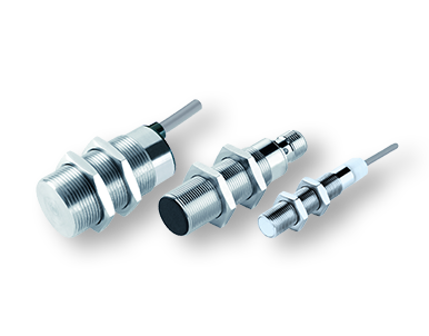


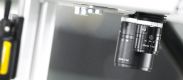


Измерительные датчики Omron ZW

- Компактные размеры и малый вес
- Высокая прочность корпуса
- Высокая стабильность измерений при работе с различными материалами
Компактные размеры и малый вес, размер датчика всего 1/8 от размера стандартного измерительного датчика.

Благодаря отсутствию электронных частей в самом сенсоре, достигается высокая стабильность измерений и устойчивость к магнитным и электрическим помехам.

Информация для заказа
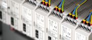
Датчик

|

|

|
|||
| Модель | ZW-S20 | ZW-S30 | ZW-S40 | ||
| Диапазон измерений | 20±1 мм | 30±3.5 мм | 40±6 мм | ||
| Диаметр пятна лума | 40 μm диа. | 60 μm диа. | 80 μm диа.. | ||
| Статическое разрешение | 0.25 μm | 0.25 μm | 0.25 μm | ||
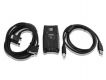
Усилитель
| Вид | Напряжение питания | Тип выхода | Модель |
|---|---|---|---|

|
24 VDC | NPN | ZW-C10T |
| ZW-C10AT | |||
| PNP | ZW-C15T | ||
| ZW-C15AT |
Кабели
| Вид | Описание | Длина кабеля | Модель |
|---|---|---|---|
| Сенсор - КонтроллерОптоволоконный кабель расширения (гибкий кабель) (Оптоволоконный адаптер ZW-XFC предоставляется) | 2 м | ZW-XF02R | |
| 5 м | ZW-XF05R | ||
| 10 м | ZW-XF10R | ||
| 20 м | ZW-XF20R | ||
| 30 м | ZW-XF30R | ||
| Оптоволоконный адаптер(между датчиком с кабелем оптоволоконный кабелем расширения) | — | ZW-XFC | |
| Параллельный кабель | 2 м | ZW-XCP2 | |
| Кабель RS-232C Для ПК | 2 м | ZW-XRS2 | |
| Кабель RS-232CДля ПЛК/программированного терминала | 2 м | ZW-XPT2 |
Характеристики
Sensor head
| Item | ZW-S07 | ZW-S20 | ZW-S30 | ZW-S40 | ZW-SR07 | ZW-SR20 | ZW-SR40 | |
|---|---|---|---|---|---|---|---|---|
| Measuring center distance | 7 mm | 20 mm | 30 mm | 40 mm | 7 mm | 20 mm | 40 mm | |
| Measuring range | ±0.3 mm | ±1 mm | ±3 mm | ±6 mm | ±0.3 mm | ±1 mm | ±6 mm | |
| Static resolution | 0.25 µm | 0.25 µm | 0.25 µm | 0.25 µm | 0.25 µm | 0.25 µm | 0.25 µm | |
| Linearity | ±0.8 µm | ±1.2 µm | ±4.5 µm | ±7.0 µm | ±1.1 µm | ±1.6 µm | ±9.3 µm | |
| Spot diameter | Near | 20 µm dia. | 45 µm dia. | 70 µm dia. | 90 µm dia. | 20 µm dia. | 45 µm dia. | 90 µm dia. |
| Center | 18 µm dia. | 40 µm dia. | 60 µm dia. | 80 µm dia | 18 µm dia. | 40 µm dia. | 80 µm dia | |
| Far | 20 µm dia. | 45 µm dia. | 70 µm dia. | 90 µm dia | 20 µm dia. | 45 µm dia. | 90 µm dia | |
| Measuring cycle | 500 µs to 10 ms | |||||||
| Operating ambient illumination | Illumination on object surface 10,000 lx or less: incandescent light | |||||||
| Ambient temperature range | Operating: 0 to 50°C, Storage: −15 to 60°C (with no icing or condensation) |
|||||||
| Ambient humidity range | Operating and storage: 35% to 85% (with no condensation) |
|||||||
| Degree of protection | IP40 (IEC60529) | |||||||
| Vibration resistance (destructive) | 10 to 150 Hz, 0.35 mm single amplitude, 80 min each in X, Y, and Z directions | |||||||
| Shock resistance (destructive) | 150 m/s2 3 times each in six directions (up/down, left/right, forward/backward) | |||||||
| Temperature characteristic | 0.6 µm/°C (0.45 μm/°C) |
1.5 µm/°C (1.0 μm/°C) |
2.8 µm/°C (2.0 μm/°C) |
4.8 µm/°C (3.8 μm/°C) |
0.6 µm/°C (0.45 μm/°C) |
1.5 µm/°C (1.0 μm/°C) |
4.8 µm/°C (3.8 μm/°C) |
|
| Materials | Case: aluminum die-cast Fiber cable sheat: PVC Calibration ROM: PC |
|||||||
| Fiber cable length | 0.3 m, 2 m (Flex-resistant cable) | |||||||
| Fiber cable minimum bending radius | 20 mm | |||||||
| Insulation resistance (Calibration ROM) | Between case and all terminals: 20 MΩ (by 250 V megger) | |||||||
| Dielectric strength (Calibration ROM) | Between case and all terminals: 1,000 VAC, 50/60 Hz, 1 min | |||||||
| Weight | Approx. 105 g (Chassis, fiber cable total) | |||||||
| Accessories included with sensor head | Instruction sheet, Fixing screw (M2) for Calibration ROM, Precautions for correct use | |||||||
Automation software Sysmac Studio
System requirements
| Item | Condition |
|---|---|
| Operating system (OS), | Windows XP (Service Pack 3 or higher, 32-bit version)/Vista(32-bit version)/7(32-bit/64-bit version) |
| CPU | Windows computers with Celeron 540 (1.8 GHz) or faster CPU. Core i5 M520 (2.4 GHz) or equivalent or faster recommended |
| Main memory | 2 GB min. |
| Recommended video memory/video card for using 3D motion trace | Video memory: 512 MB min. Video card: Either of the following video cards: • NVIDIA GeForce 200 Series or higher • ATI RadeonHD5000 Series or higher |
| Hard disk | At least 1.6 GB of available space |
| Display | XGA 1024 x 768, 16 million colors. WXGA 1280 x 800 min. recommended |
| Disk drive | DVD-ROM drive |
| Communication ports | USB port corresponded to USB 2.0, or Ethernet port |
| Supported languages | Japanese, English, German, French, Italian, Spanish, simplified Chinese, traditional Chinese, Korean |
Setting software Smart Monitor ZW ZW-SW101
System requirements
| Item | Condition |
|---|---|
| Operating System(OS) | Windows 7 (32 or 64-bit version) Windows XP (Service Pack3 or more, 32-bit version) |
| CPU | Intel Pentium III, 850 MHz or more (2 GHz or more is recommended.) |
| Main memory | 1 GB or more |
| Hard disk | 50 MB or more |
| Display | 1024 x 768 dots or more, 16 million colors or more |
| Supported languages | Japanese/English |
| Communication port | Ethernet port |
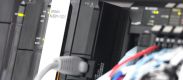
Controller
| Item | ZW-CE10T | ZW-CE15T | |||
|---|---|---|---|---|---|
| Input/Output type | NPN | PNP | |||
| Number of connected sensor heads | 1 per Controller | ||||
| Sensor head compatibility | Available | ||||
| Light source for measurement | White LED | ||||
| Segment display | Main display | 11-segment red display, 6 digits | |||
| Sub-display | 11-segment green display, 6 digits | ||||
| LED display | Status indicators | HIGH (orange), PASS (green), LOW (orange), STABILITY (green), ZERO (green), ENABLE (green), THRESHOLD-H (orange), THRESHOLD-L (orange), RUN (green) |
|||
| EtherCAT indicators | L/A IN (Link Activity IN) (green), L/O OUT (Link Activity OUT) (green), ECAT RUN (green), ECAT ERR (red) | ||||
| External interface | Ethernet | 100BASE-TX, 10BASE-T, No-protocol communications (TCP/UDP), EtherNet/IPTM | |||
| EtherCAT | EtherCAT-specific protocol 100BASE-TX | ||||
| RS-232C | 115,200 bps max. | ||||
| Analog output terminal block | Analog voltage output (OUT1V) | -10 to 10 V, output impedance: 100 Ω | |||
| Analog current output (OUT1A) | 4 to 20 mA, maximum load resistance: 300 Ω | ||||
| 32-pole extension connector |
Judgment output (HIGH1/PASS1/LOW1) |
Transistor output system Output voltage: 21.6 to 30 VDC Load current: 50 mA or less Residual voltage when turning ON: 1.2 V or less Leakage voltage when turning OFF: 0.1 mA or les |
|||
| BUSY output (BUSY1) | |||||
| ALARM output (ALARM1) | |||||
| ENABLE output (ENABLE) | |||||
| LED OFF input (LED OFF1) | DC input system Input voltage: 24 VDC -10% (21.6 to 26.4 VDC) Input current: 7 mA Typ. (24 VDC) Voltage/Current when turning ON: 19 V/3 mA or more Voltage/Current when turning OFF: 5 V/1 mA or less |
||||
| ZERO RESET input (ZERO) | |||||
| TIMING output (TIMING1) | |||||
| RESET output (RESET1) | |||||
| Bank | Selected bank output (BANK_OUT 1 to 3) |
Transistor output system Output voltage: 21.6 to 30 VDC Load current: 50 mA or less Residual voltage when turning ON: 1.2 V or less Leakage voltage when turning OFF: 0.1 mA or less |
|||
| Selected bank input (BANK_SEL 1 to 3) |
DC input system Input voltage: 21.6 to 26 VDC Input current: 7 mA Typ. (24 VDC) Voltage/Current when turning ON: 19 V/3 mA or more Voltage/Current when turning OFF: 5 V/1 mA or less |
||||
| Main functions | Exposure time | Auto/Manual | |||
| Measuring cycle | 500 µs to 10 ms | ||||
| Material setting | Standard/Mirror/Diffusion surfaces | ||||
| Measurement Item | Height/Thickness/Calculation | ||||
| Filtering | Median/Average/Differentiation/High pass/Low pass/Band pass | ||||
| Outputs | Scaling/Different holds/Zero reset/Logging for a measured value | ||||
| Display | Measured value/Threshold value/Analog output voltage or current value/Judgment result/Resolution/Exposure time | ||||
| Number of configurable banks | Max. 8 banks | ||||
| Task process | Multi-task (up to 4 tasks per bank) | ||||
| System | Save/Initialization/Display measurement information/Communication settings/Sensor Head calibration/Key-lock/ Trigger-key input |
||||
| Ratings | Power supply voltage | 21.6 to 26.4 VDC (including ripple) | |||
| Current consumption | 600 mA max. | ||||
| Insulation resistance | Across all lead wires and controller case: 20 MΩ (by 250 V megger) | ||||
| Dialectic strength | Across all lead wires and controller case: 1,000 VAC, 50/60 Hz, 1 min. | ||||
| Environmental | Degree of protection | IP20 (IEC60529) | |||
| Vibration resistance (destructive) | 10 to 55 Hz, 0.35-mm single amplitude, 50 min each in X, Y, and Z directions | ||||
| Shock resistance (destructive) | 150 m/s2, 3 times each in six directions (up/down, left/right, forward/backward) | ||||
| Ambient temperature | Operating: 0 to 40°C Storage: -15 to 60°C (with no icing or condensation) |
||||
| Ambient humidity | Operating and storage: 35% to 85% (with no condensation) | ||||
| Grounding | D-type grounding (Grounding resistance of 100 Ω or less)
Note: For conventional Class D grounding |
||||
| Materials | Case: PC | ||||
| Weight | Approx. 750 g (main unit only), approx. 150 g (Parallel cable) | ||||
| Accessories included with controller | Instruction sheet, Member registration sheet, Parallel cable ZW-XCP2E | ||||
ZW series EtherCAT communications specifications
| Item | Specification |
|---|---|
| Communications standard | IEC61158 Type12 |
| Physical layer | 100BASE-TX (IEEE802.3) |
| Connectors | RJ45 x 2 ECAT IN: EtherCAT input ECAT OUT: EtherCAT output |
| Communications media | Category 5 or higher (cable with double, aluminum tape and braided shielding) is recommended. |
| Communications distance | Distance between nodes: 100 m max. |
| Process data | Variable PDO mapping |
| Mailbox (CoE) | Emergency messages, SDO requests, SDO responses, and SDO information |
| Distributed clock | Synchronization in DC mode. |
| LED display | L/A IN (Link/Activity IN) x 1, AL/A OUT (Link/Activity OUT) x 1, AECAT RUN x 1, AECAT ERR x 1 |
В этой категории нет товаров